Thz Lab Log [0] - Running Radar usecases on TI AWR 2243 EVM using an SD Card
- This blog expects the readers’ familiarity with the cascade radar sensor or the mmWave studio, preferably on the windows platform. Although TI has documentation on how to do the following, I had to spend a fair amount of time on the forum to get things working as intended. Thanks to some swift responses on the forum, the radar saw first images. I hope this helps you cut down the additional time you’ll otherwise spend on debugging issues whilst trying to run use cases.
tldr; there’s a checklist in the end.
AWR2243
The Texas Instruments AWR2243 mmWave Cascade Radar evaulation board is a 4 chip FMCW (Frequency Modulated Continuous Wave) radar sensor that supports long range beam forming applications and short range MIMO applications such as object detection, long range radar etc.,The evaluation board boasts an antenna field of view of abuot +-70 degrees with an angular resolution of 1.4 degrees which open doors to a plethora of applications.
An example of the AWR 2243 being used to estimate and track the position of an object at or about a distance of 350 meters is mentioned here.
The radar is powered by a TDA2xx capture card that has a Dual Cortex A-15 SOC, a Dual DSP C66x and several other high performance processing capabilities to enable several real time applications.
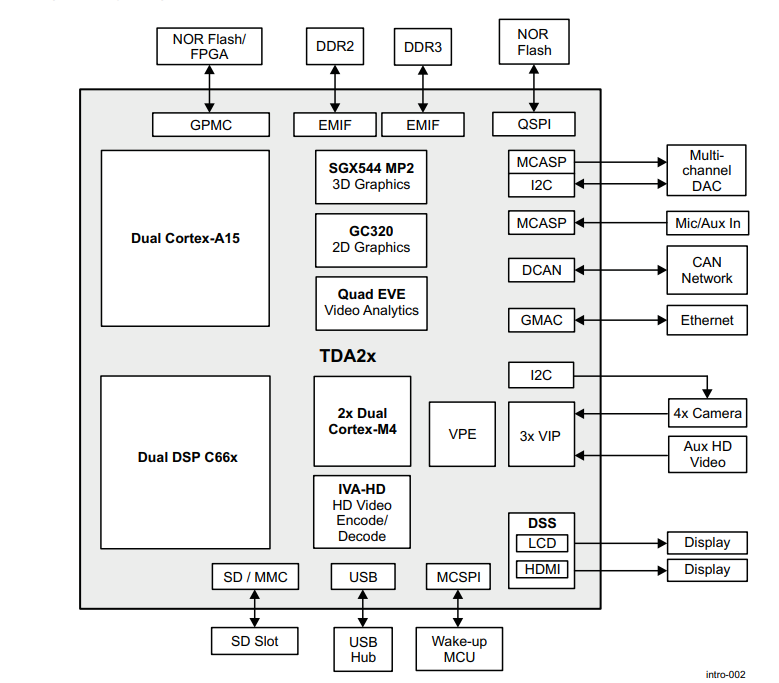
TDA 2xx Block Diagram, credits: Texas Instruments
While this article doesn’t cover the entire range of applications that, it is aimed at giving the reader an overview, rather some useful tips there by reducing the time spent researching and debugging errors. I was succesfully able to run the existing use cases provided in the Radar SDK using an SD card and the steps are discussed below.
The Radar SDK
The PROCESSOR-SDK-RADAR is one of the two multi-processor software development kits that is available for creating, accessing, processing multiple data flows using the evaluation kits that are powered by the Ti TDAxx capture cards. More about the SDK is described in detail on the website.
The software libraries and examples that will help us navigate (literally) working with EVM board and give us the necessary tools for developing our own use cases.
Once installed, we can access list of use cases under the path ../PROCESSOR_SDK_RADAR_03_08_00/vision_sdk/docs/Radar/Processor_SDKRadar_Usecases.xslx.
 Installation Instructions
The Radar SDK can be downloaded for free under the name PROCESSOR_SDK_CASCADE_RADAR here.
The page has several versions, make sure that you install the latest update for your version of the board. We have the kit with TDA2xx at our lab so the I installed the latest update that supports it, i.e., PROCESSOR_SDK_RADAR_03_08_00_00.exe
For windows machines there is a character length limit in the environment variable setup. To eliminate any possible hassles, the official documentation suggests that the SDK be installed at a top level directory i.e., preferably the root folder of your storage drive.
 Building the Application
Given we want to load the firmware with custom use case or in this case, the sample use cases using an SD Card, we need some sort of binary/application image that the capture card can use to control the radar. The process of building the application for sample use cases begins with setting up rules in the Rules.make file under PROCESSOR_SDK_RADAR_03_08_00/vision_sdk/build/ folder.
 Usecase configuration
The Rules.make file sets up the necessary environment required for building the application/use cases. Depending on what kind of use cases we want to run we need to make sure that the appropriate variables in the make file are setup properly.
I wanted to run the sample use cases for radar two and thus the following configuration.
MAKEAPPNAME?=apps
I was building these use cases using a
windowsmachine and thus set the make configuration variable as follows. If you are using a Linux Machine, please make an appropriate choice from the list of available configurations.
MAKECONFIG?=tda2xx_cascade_bios_radar
There are 3 sample use cases we can run in this configuration namely:
- Cascade Radar Capture + Null
- Cascade Radar Capture + Radar Object Detection (DSP) + Network Tx
- Cascade Radar + FFT (EVE) + Tx Beam Form Static Map (DSP) + Network Tx
Building firmware is now a task of running a few straight forward commands that will give us an AppImage and an MLO file that act as boot loader for the hardware.
 Verifying Network Configuration
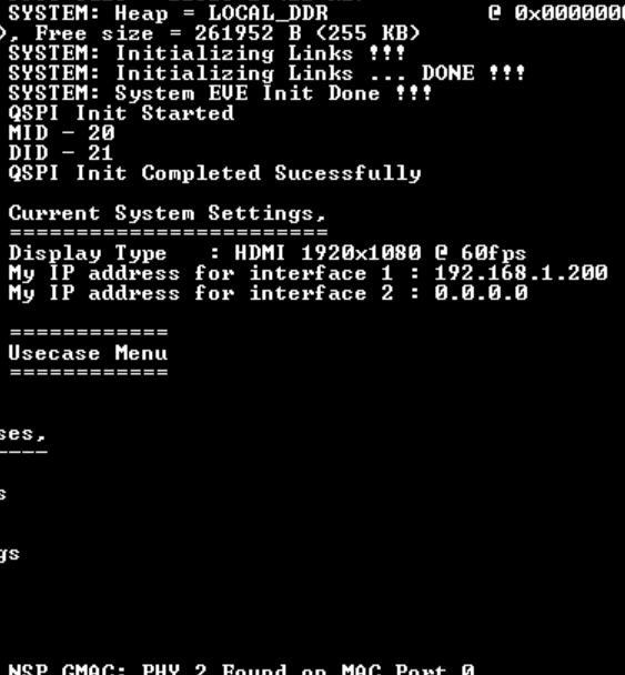
One of the things that the official docs miss out on informing us is the network configuration. After dabbling with build steps and obtaining the required binary files, I had one last issue to resolve. That is, when checking the serial communication terminal I saw that the interface was showing 0.0.0.0 as it’s address. My preliminary research I indicated that it might have been setup to use a DHCP style allocation (This is actually the case, and is documented in one of the issues referenced in the end).
Through some more digging on the forum, I found that the NDK_Config.cfg file under PROCESSOR_SDK_RADAR_xx_yy_zz/vision_sdk/links_fw/src/rtos/bios_app_common/tda2xx/cfg handles the network interface setup and ip allocation business.
By setting the enableStaticIPEth0 = 1 and looking for the Ip.address variable under a conditional on line 221 on the config, I could see that the ipaddress allocated to the Capture Card is 192.168.1.200. Setting the ipv4 on the computer as 192.168.1.101 with a subnet mask of 255.255.255.0 and DNS to 192.168.1.1 completes the network configuration required. (Refer to Network Configuration Thread in references section)
192.168.33.101and DNS as192.168.33.1. While running the MATLAB code as shown in a later step replace the device ip as192.168.33.180
Inorder to avoid build time errors, I went into the binaries folder, backed up the older version and deleted the files. I then rebuilt all of the dependencies, application, MLO and AppImage files, loaded them onto the SD Card, and voila, the IP address was correctly allocated.
At this point we are not only ready to start running our usecases but also can see some real time output by running the provided MATLAB script(s).
 Commands to Build the Firmware
Run the following commands one after the other to build the firmware.
$ gmake -s -j2 depend # building dependencies
$ gmake -s -j2 # building the firmware itself
$ gmake -s sbl #building the MLO file
$ gmake -s appimage #building appimage
The final products of this process are two files that we need to copy on to the SD card.
- MLO file (found at
PROCESSOR_SDK_RADAR_xx_yy_zz/vision_sdk/binaries/apps/tda2xx_cascade_bios_radar/sbl/sd/opp_xxx). There are 4 final folders that contain different MLO files. These folders indicate the operating performance point of the file. Any of them can be used for the device. - App Image (found at
PROCESSOR_SDK_RADAR_xx_yy_zz/vision_sdk/binaries/apps/tda2xx_cascade_bios_radar/vision_sdk/bin/tda2xx-evm/sbl_boot/)
 Serial Communication
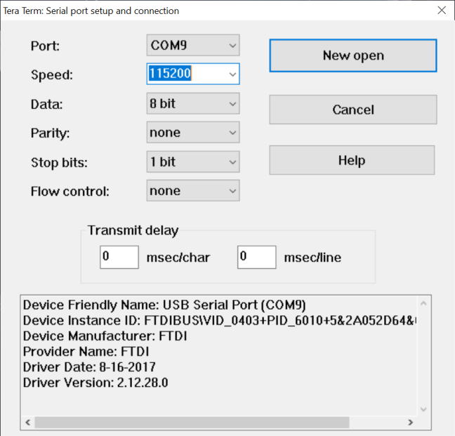
The TDA2xx communicates over the LAN for tranferring the capture(d) data and over a serial port to display and take in control instructions with these custom firmware images. It is advised that a serial communication emulator such as TeraTerm be installed and the following settings be changed.
- Go to
Setupmenu, selectSerialoption from the list of options. - Change the settings in the serial connection settings window as shown in the picture below.
Note
- The serial port number might vary from machine to machine. Upon connecting the TDA2xx boards, you would probably be able to see two new serial ports. Choose the one with lower numerical value among them. If you do not know how to locate your serial port, please refer to/search for
checking for serial connection devices on device manager. - It is advised that the power on the board be disconnected while doing this step so as to be able to see the boot sequence messages once the setup is complete and the board is turned on.
- The serial port number might vary from machine to machine. Upon connecting the TDA2xx boards, you would probably be able to see two new serial ports. Choose the one with lower numerical value among them. If you do not know how to locate your serial port, please refer to/search for
After powering on the device the teraterm window should look something like below. It will show you the messages from device startup sequence, and top level use case selection menu.
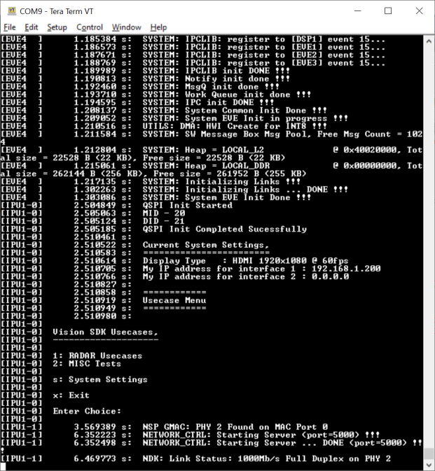
Running the Usecases
I want to run the Radar Usecases and thus, I selected 1 on this menu.

If you have dwelled into the use case configuration source code, you might have seen these three options. I am now going to try and run the Tx Beam forming i.e., option b.
This leads us to a file/network transfer protocol menu as follows.
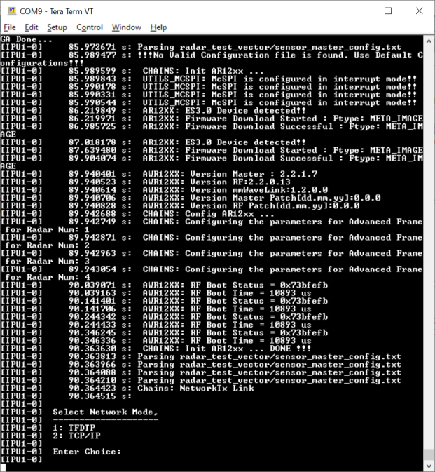
The MATLAB code provided in the examples for displaying the output of this firmware image running on the radar board only supports TFDTP and thus we select that choice 1 on this menu.
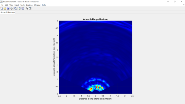
Moving on, we can now run the provided MATLAB gui to see what the Radar is actually capturing. These scripts can be found under respective use case names in the following path. ..\PROCESSOR_SDK_RADAR_03_08_00_00\vision_sdk\apps\src\rtos\radar\src\usecases\... Since this we’re running the beam forming example the path would be
C:\PROCESSOR_SDK_RADAR_03_08_00_00\vision_sdk\apps\src\rtos\radar\src\usecases\cascade_radar_beam_form and the script is called radar_cascade_bf_demo.m.
If you are trying to navigate to this folder from an existing instance of MATLAB, make sure to add this path to MATLABS env, using the
add to pathoption.
Navigate to the command window and use the following command to run the script.
>> radar_cascade_bf_demo('192.168.1.200', '192.168.1.101','BB-44-33-22-11-AA', 'TI', 5, 1)
Command Break Down
radar_cascade_bf_demo(‘Target Ip Address’, ‘Host IP Address’,’Host MAC Address’, ‘Platform Name’, ‘Range Depth in Meters’, ‘Profile Number’)
Upon running the above, we should see a figure, that updates in real time.
If you face any errors in reaching until this step, or in any of the above steps, please refer to the links in References section or write to me at email the email address in the bottom of this page.
 If there were a check list
| S.no | Step | Check |
|---|---|---|
| 1. | Format the SD Card to have a FAT32 Filesystem. | |
| 2. | Check the MAKECONFIG variable in Rules.make. |
|
| 3. | Check the NDK_Config.cfg file for network settings. |
|
| 4. | Build Dependencies. | |
| 5. | Build the application. | |
| 6. | Build an MLO File. | |
| 7. | Build the AppImage. | |
| 8. | Load the AppImage and MLO files on the SD Card. | |
| 9. | Check DIP Switches on the Capture Card. | |
| 10. | Load the SD Card into the board. | |
| 11. | Connect to Serial interface | |
| 12. | Run the usecases. | |
| 13. | View the output on MATLAB. |
 Road Ahead
- Using Calibration files on SD Card.
- Deciphering the Network Stack.
- Applying Custom Algorithms for Beam Forming Image Plotting.
- Custom use cases.